ROS Build a Custom Robot
In this Chapter we will look at how to build a gazebo model of a robot given the mechanical design. The following topics will be covered:
Building up the model in Gazebo
Adding a ROS control interface to the model
Building a Gazebo Model
A model in Gazebo is made of links which are connected through joints. Since this is a ROS lecture, we use URDF files to declare the model. There are other ways of doing it, which will not be covered. In general it is important to notice that all distances are generally in meters and all angles in radian.
Link definition
The official documentation of how to define a link in urdf can be found here.
Box
<xacro:property name="length" value="1.0" />
<xacro:property name="width" value="1.0" />
<xacro:property name="height" value="1.0" />
<xacro:property name="density" value="1" />
<xacro:property name="mass" value="${length*height*width*density}" />
<link name="link_name">
  <visual>
    <origin xyz="0 0 0" rpy="0 0 0"/>
    <geometry>
      <box size="${length} ${width} ${height}"/>
    </geometry>
  </visual>
  <collision>
    <origin xyz="0 0 0.0" rpy="0 0 0"/>
    <geometry>
      <box size="${length} ${width} ${height}"/>
    </geometry>
  </collision>
  <inertial>
    <origin xyz="0 0 0" rpy="0 0 0"/>
    <mass value="${mass}"/>
    <inertia
      ixx="${mass*(pow(height,2) + pow(width,2))/12}" ixy="0.0" ixz="0.0"
      iyy="${mass*(pow(length,2) + pow(height,2))/12}" iyz="0.0"
      izz="${mass*(pow(length,2) + pow(width,2))/12}"/>
  </inertial>
</link>
Box Macro Definition
<xacro:macro name="link_box" params="link_name length width height density:=1 mesh_name:='nofile' *origin_vis *origin_col *origin_inertial">
  <xacro:property name="mass" value="${length*height*width*density}" />
  <link name="${link_name}">
    <visual>
      <!-- <origin xyz="0 0 0" rpy="0 0 0"/> -->
      <xacro:insert_block name="origin_vis" />
      <geometry>
        <xacro:if value="${mesh_name == 'nofile'}">
          <box size="${length} ${width} ${height}"/>
        </xacro:if>
        <xacro:unless value="${mesh_name == 'nofile'}">
          <mesh filename="${mesh_name}" />
        </xacro:unless>
      </geometry>
    </visual>
    <collision>
      <!-- <origin xyz="0 0 0.0" rpy="0 0 0"/> -->
      <xacro:insert_block name="origin_col" />
      <geometry>
        <box size="${length} ${width} ${height}"/>
      </geometry>
    </collision>
    <inertial>
      <!-- <origin xyz="0 0 0" rpy="0 0 0"/> -->
      <xacro:insert_block name="origin_inertial" />
      <mass value="${mass}"/>
      <inertia
        ixx="${mass*(pow(height,2) + pow(width,2))/12}" ixy="0.0" ixz="0.0"
        iyy="${mass*(pow(length,2) + pow(height,2))/12}" iyz="0.0"
        izz="${mass*(pow(length,2) + pow(width,2))/12}"/>
    </inertial>
  </link>
</xacro:macro>
Box Macro Usage
<xacro:link_box link_name="LINK_NAME" length="0.1" width="0.1" height="0.1" density="1" mesh_name="nofile">
  <!-- origin visual -->
  <origin xyz="0 0 0" rpy="0 0 0"/>
  <!-- origin collision -->
  <origin xyz="0 0 0" rpy="0 0 0"/>
  <!-- origin interia -->
  <origin xyz="0 0 0" rpy="0 0 0"/>
</xacro:link_box>
Cylinder
<xacro:property name="radius" value="1.0" />
<xacro:property name="length" value="1.0" />
<xacro:property name="density" value="1.0" />
<xacro:property name="mass" value="${pi*length*pow(radius,2)*density}" />

<link name="LINK_NAME">
  <visual>
    <origin xyz="0 0 0" rpy="0 0 0"/>
    <geometry>
      <cylinder length="${length}" radius="${radius}"/>
    </geometry>
  </visual>
  <collision>
    <origin xyz="0 0 0" rpy="0 0 0"/>
    <geometry>
      <cylinder length="${length}" radius="${radius}"/>
    </geometry>
  </collision>
  <inertial>
    <origin xyz="0 0 0" rpy="0 0 0"/>
    <mass value="${mass}"/>
    <inertia
      ixx="${mass*(3*pow(radius,2)+pow(length,2))/12}" ixy="0.0" ixz="0.0"
      iyy="${mass*(3*pow(radius,2)+pow(length,2))/12}" iyz="0.0"
      izz="${mass*pow(radius,2)/2}"/>
  </inertial>
</link>
Cylinder Macro Definition
<xacro:macro name="link_cylinder" params="link_name radius length density:=1 mesh_name:='nofile' *origin_vis *origin_col *origin_inertial">
  <xacro:property name="mass" value="${pi*length*pow(radius,2)*density}" />
  <link name="${link_name}">
    <visual>
      <!-- <origin xyz="0 0 0" rpy="0 0 0"/> -->
      <xacro:insert_block name="origin_vis" />
      <geometry>
        <xacro:if value="${mesh_name == 'nofile'}">
          <cylinder length="${length}" radius="${radius}"/>
        </xacro:if>
        <xacro:unless value="${mesh_name == 'nofile'}">
          <mesh filename="${mesh_name}" />
        </xacro:unless>
      </geometry>
    </visual>
    <collision>
      <!-- <origin xyz="0 0 0" rpy="0 0 0"/> -->
      <xacro:insert_block name="origin_col" />
      <geometry>
        <cylinder length="${length}" radius="${radius}"/>
      </geometry>
    </collision>
    <inertial>
      <!-- <origin xyz="0 0 0" rpy="0 0 0"/> -->
      <xacro:insert_block name="origin_inertial" />
      <mass value="${mass}"/>
      <inertia
        ixx="${mass*(3*pow(radius,2)+pow(length,2))/12}" ixy="0.0" ixz="0.0"
        iyy="${mass*(3*pow(radius,2)+pow(length,2))/12}" iyz="0.0"
        izz="${mass*pow(radius,2)/2}"/>
    </inertial>
  </link>
</xacro:macro>
Cylinder Macro Usage
<xacro:link_cylinder link_name="LINK_NAME" radius="0.1" length="0.1" density="1" mesh_name="nofile" >
  <!-- origin visual -->
  <origin xyz="0 0 0" rpy="0 0 0"/>
  <!-- origin collision -->
  <origin xyz="0 0 0" rpy="0 0 0"/>
  <!-- origin interia -->
  <origin xyz="0 0 0" rpy="0 0 0"/>
</xacro:link_cylinder>
Sphere
<xacro:property name="radius" value="1.0" />
<xacro:property name="density" value="1.0" />
<xacro:property name="mass" value="${(4/3)*pi*pow(radius,3)}" />
<link name="LINK_NAME">
  <visual>
    <origin xyz="0 0 0" rpy="0 0 0"/>
    <geometry>
      <sphere radius="${radius}"/>
    </geometry>
  </visual>
  <collision>
    <origin xyz="0 0 0.0" rpy="0 0 0"/>
    <geometry>
      <sphere radius="${radius}"/>
    </geometry>
  </collision>
  <inertial>
    <origin xyz="0 0 0" rpy="0 0 0"/>
    <mass value="${mass}"/>
    <inertia
      ixx="${2*mass*pow(radius,2)/5}" ixy="0.0" ixz="0.0"
      iyy="${2*mass*pow(radius,2)/5}" iyz="0.0"
      izz="${2*mass*pow(radius,2)/5}"/>
  </inertial>
</link>
Sphere Macro Definition
<xacro:macro name="link_sphere" params="link_name radius density:=1 mesh_name:='nofile' *origin_vis *origin_col *origin_inertial">
  <xacro:property name="mass" value="${(4/3)*pi*pow(radius,3)}" />
  <link name="${link_name}">
    <visual>
      <!-- <origin xyz="0 0 0" rpy="0 0 0"/> -->
      <xacro:insert_block name="origin_vis" />
      <geometry>
        <xacro:if value="${mesh_name == 'nofile'}">
          <sphere radius="${radius}"/>
        </xacro:if>
        <xacro:unless value="${mesh_name == 'nofile'}">
          <mesh filename="${mesh_name}" />
        </xacro:unless>
      </geometry>
    </visual>
    <collision>
      <!-- <origin xyz="0 0 0.0" rpy="0 0 0"/> -->
      <xacro:insert_block name="origin_col" />
      <geometry>
        <sphere radius="${radius}"/>
      </geometry>
    </collision>
    <inertial>
      <!-- <origin xyz="0 0 0" rpy="0 0 0"/> -->
      <xacro:insert_block name="origin_inertial" />
      <mass value="${mass}"/>
      <inertia
        ixx="${2*mass*pow(radius,2)/5}" ixy="0.0" ixz="0.0"
        iyy="${2*mass*pow(radius,2)/5}" iyz="0.0"
        izz="${2*mass*pow(radius,2)/5}"/>
    </inertial>
  </link>
</xacro:macro>
Sphere Macro Usage
<xacro:link_sphere link_name="LINK_NAME" radius="0.1" density="1" mesh_name="nofile">
  <!-- origin visual -->
  <origin xyz="0 0 0" rpy="0 0 0"/>
  <!-- origin collision -->
  <origin xyz="0 0 0" rpy="0 0 0"/>
  <!-- origin interia -->
  <origin xyz="0 0 0" rpy="0 0 0"/>
</xacro:link_sphere>
Inertial Parameters
An accurate simulation requires accurate dynamic properties of the links. These are defined by the inertial parameters. An official guide on the Gazebo website can be found here. An online tool (mesh cleaner) to calculate the inertial parameters for mesh files automatically can be found here. When using simple shapes, the previous example code for the different links automatically calculates the inertial parameters assuming you use the defined variables. A list of formulas to calculate the inertial parameters for simple shapes can be found here.
Make sure the center of mass is in the accurate location. For simple shapes it is in the center of the link, which means, as long as the <origin> inside the <intertail> tag is the same as the <origin> in the <collision> tag it should be correct.
Joint definition
The official documentation of how to define a joint in urdf can be found here. Some important parts of the joint definition are the following:
<axis>: defines which axis is used by the joint for movement.
<limit>
effort maximum torque/force measured in [Nm]
velocity maximum speed measured in [m/s] for primatic joints and [rad/s] for revolute joints
lower minimum allowed joint angle/position measured in [m] for prismatic joints and [rad] for revolute joints.
upper maximum allowed joint angle/position
Continuous Joint
Continuous joints rotate around the defined axis (1 degree of freedom).
<joint type="continuous" name="JOINT_NAME">
  <origin xyz="0 0 0" rpy="0 0 0"/>
  <child link="CHILD_LINK_NAME"/>
  <parent link="PARENT_LINK_NAME"/>
  <axis xyz="0 0 1" rpy="0 0 0"/>
  <limit effort="100" velocity="100"/>
</joint>
Revolute Joint
Revolute joints also rotate around the defined axis (1 degree of freedom) similar to continuous joints but have a defined minimum and maximum joint angle in [rad].
<joint type="revolute" name="JOINT_NAME">
  <origin xyz="0 0 0" rpy="0 0 0"/>
  <child link="CHILD_LINK_NAME"/>
  <parent link="PARENT_LINK_NAME"/>
  <axis xyz="0 0 1" rpy="0 0 0"/>
  <limit effort="100" velocity="100" lower="-${pi}" upper="${pi}"/>
</joint>
Prismatic Joint
Prismatic joints move along the defined axis (1 degree of freedom) and have a minimum and maximum joint position definedin [m].
<joint type="prismatic" name="JOINT_NAME">
  <origin xyz="0 0 1.0" rpy="0 0 0"/>
  <child link="CHILD_LINK_NAME"/>
  <parent link="PARENT_LINK_NAME"/>
  <axis xyz="0 0 1" rpy="0 0 0"/>
  <limit effort="100" velocity="100" lower="-1.0" upper="1.0"/>
</joint>
Exercise
Download the ROS package used for the exercise from this link. After unzipping it, copy it to the VM in catkin_ws/src/. Run the following commands in a terminal window:
cd ~/catkin_ws/
catkin_make
Copy the following code into the file “mobile_manipulator_robot.urdf.xacro” located in the “urdf” folder of the ROS package:
<?xml version='1.0'?>

<robot name="mobile_manipulator_robot" xmlns:xacro="http://www.ros.org/wiki/xacro">
  <xacro:include filename="$(find custom_robot_tutorial)/urdf/common_macros.xacro" />

  <gazebo>
    <static>true</static>
  </gazebo>

<!--############################### -->
<!-- MOBILE PLATFORM -->
<!--############################### -->
  <origin xyz="0 0 0.15" rpy="0 0 0"/>
  <link name="base_footprint"/>

  <joint name="base_joint" type="fixed">
    <parent link="base_footprint"/>
    <child link="mobile_body_link" />
    <origin xyz="0 0 0.0" rpy="0 0 0"/>
  </joint>


  <!-- MOBILE BASE -->
  <!-- ==================================== -->
  <xacro:link_box link_name="mobile_body_link" length="0.65" width="0.4" height="0.2" mesh_name="package://custom_robot_tutorial/meshes/base_mesh.stl">
    <!-- origin visual -->
    <origin xyz="0 0 0" rpy="0 0 0"/>
    <!-- origin collision -->
    <origin xyz="0 0 0" rpy="0 0 0"/>
    <!-- origin interia -->
    <origin xyz="0 0 0" rpy="0 0 0"/>
  </xacro:link_box>


  <!-- FRONT LEFT WHEEL -->
  <!-- ==================================== -->
  <joint type="continuous" name="wheel_front_left_joint">
    <origin xyz="0.200 0.255 -0.050" rpy="-${pi/2} 0 0"/>
    <child link="wheel_front_left_link"/>
    <parent link="mobile_body_link"/>
    <axis xyz="0 0 1" rpy="0 0 0"/>
    <limit effort="100" velocity="100"/>
  </joint>

  <xacro:link_cylinder link_name="wheel_front_left_link" radius="0.1" length="0.1" density="1" mesh_name="package://custom_robot_tutorial/meshes/wheel_mesh.stl" >
    <!-- origin visual -->
    <origin xyz="0 0 0" rpy="0 0 0"/>
    <!-- origin collision -->
    <origin xyz="0 0 0" rpy="0 0 0"/>
    <!-- origin interia -->
    <origin xyz="0 0 0" rpy="0 0 0"/>
  </xacro:link_cylinder>

  <!-- FRONT RIGHT WHEEL -->
  <!-- ==================================== -->
  <joint type="continuous" name="wheel_front_right_joint">
    <origin xyz="0.200 -0.255 -0.050" rpy="-${pi/2} 0 0"/>
    <child link="wheel_front_right_link"/>
    <parent link="mobile_body_link"/>
    <axis xyz="0 0 1" rpy="0 0 0"/>
    <limit effort="100" velocity="100"/>
  </joint>

  <xacro:link_cylinder link_name="wheel_front_right_link" radius="0.1" length="0.1" density="1" mesh_name="package://custom_robot_tutorial/meshes/wheel_mesh.stl" >
    <!-- origin visual -->
    <origin xyz="0 0 0" rpy="0 0 0"/>
    <!-- origin collision -->
    <origin xyz="0 0 0" rpy="0 0 0"/>
    <!-- origin interia -->
    <origin xyz="0 0 0" rpy="0 0 0"/>
  </xacro:link_cylinder>

</robot>
To start the Gazebo world use the following command in the terminal:
roslaunch custom_robot_tutorial mobile_manipulator.launch
To spawn the robot in the existing Gazebo world use the following terminal command:
roslaunch custom_robot_tutorial robot_spawn.launch
Start adding the missing 3 wheels to the robot model by modifying the “mobile_manipulator_robot.urdf.xacro” file. Where to place the wheels can be deducted from the following mechanical drawings:


Once you finished with adding all the wheels to the mobile platform, copy the following code into the “mobile_manipulator_robot.urdf.xacro” file just before the </robot> tag at the end of the file:
<!--############################### -->
<!-- ROBOTIC ARM -->
<!--############################### -->

  <!-- ARM BASE -->
  <!-- ==================================== -->
  <joint type="revolute" name="arm_base_joint">
    <origin xyz="0 0 0.1" rpy="0 0 0"/>
    <child link="arm_base_link"/>
    <parent link="mobile_body_link"/>
    <axis xyz="0 0 1" rpy="0 0 0"/>
    <limit effort="100" velocity="100" lower="-${pi}" upper="${pi}"/>
  </joint>

  <xacro:link_cylinder link_name="arm_base_link" radius="${0.135/2}" length="0.2" density="1" mesh_name="package://custom_robot_tutorial/meshes/arm_base_mesh.stl" >
    <!-- origin visual -->
    <origin xyz="0 0 0" rpy="0 0 0"/>
    <!-- origin collision -->
    <origin xyz="0 0 0.1" rpy="0 0 0"/>
    <!-- origin interia -->
    <origin xyz="0 0 0.1" rpy="0 0 0"/>
  </xacro:link_cylinder>

  <!-- LINK 1 -->
  <!-- ==================================== -->
  <joint type="revolute" name="link_1_joint">
    <origin xyz="0 0 0.2" rpy="-${pi/2} 0 0"/>
    <child link="link_1_link"/>
    <parent link="arm_base_link"/>
    <axis xyz="0 0 1" rpy="0 0 0"/>
    <limit effort="100" velocity="100" lower="-${pi/2}" upper="${pi/2}"/>
  </joint>

  <xacro:link_cylinder link_name="link_1_link" radius="${0.075/2}" length="0.385" density="1" mesh_name="package://custom_robot_tutorial/meshes/link_1_mesh.stl" >
    <!-- origin visual -->
    <origin xyz="0 -${0.385/2} 0" rpy="${pi/2} 0 0"/>
    <!-- origin collision -->
    <origin xyz="0 -${0.385/2} 0" rpy="${pi/2} 0 0"/>
    <!-- origin interia -->
    <origin xyz="0 -${0.385/2} 0" rpy="${pi/2} 0 0"/>
  </xacro:link_cylinder>
ROS Connection Issues
If you have done the lab with the real Turtlebot, you might have problems with starting roscore or connecting to the ROS master. To fix this, follow the following steps. Open up a terminal in your virtual machine and open the .bashrc file using the following command:
gedit ~/.bashrc
Towards the end of the file you should have a line with the following text:
export ROS_IP=SOME_IP_ADDRESS
Where SOME_IP_ADDRESS is the IP adress you had during the lab exercise. Change this text line to the following:
# export ROS_IP=127.0.0.1
export ROS_HOSTNAME=localhost
export ROS_MASTER_URI=http://localhost:11311/
Save the file and close it and all the terminals you have currently open. Once you start a new terminal the issue should be resolved. If you still have trouble don’t hesitate to contact me (Laurenz Elstner) either on canvas or discord.
Controlling the Gazebo Model
In the previous Exercise a simulation model for gazebo of a custom robot has been built. This section will continue from that point, by going through the process of adding a controller interface which makes the model movable through ROS. The completed URDF model file (mobile_manipulator_robot.urdf.xacro) can be downloaded here. All gazebo plugins will be defined in the mobile_manipulator_robot.urdf.gazebo file. Therefore, we must refence it in our xacro file by adding the following code as shown in the image below:
<xacro:include filename="$(find custom_robot_tutorial)/urdf/mobile_manipulator_robot.urdf.gazebo" />

The basic structure of the mobile_manipulator_robot.urdf.gazebo file is as follows:
<?xml version="1.0"?>
<robot>

</robot>
Mobile platform
For mobile platforms with two or four wheels, gazebo has predefined plugins. Both plugins subscribe to the “cmd_vel” ROS topic which can then be used to move the mobile robot. More information on how to publish on the “cmd_vel” topic can be found in subsection Controlling the Mobile Platform.
Differential Drive (two wheels)
The gazebo plugin for two wheeled robots is called “libgazebo_ros_diff_drive.so” and can be used by copying the following code into your mobile_manipulator_robot.urdf.gazebo file:
  <gazebo>
    <plugin name="mobile_base_controller" filename="libgazebo_ros_diff_drive.so">
      <commandTopic>cmd_vel</commandTopic>
      <odometryTopic>odom</odometryTopic>
      <odometryFrame>/odom</odometryFrame>
      <odometrySource>world</odometrySource>
      <publishOdomTF>true</publishOdomTF>
      <robotBaseFrame>LINK_NAME</robotBaseFrame>
      <publishWheelTF>false</publishWheelTF>
      <publishTf>true</publishTf>
      <publishWheelJointState>true</publishWheelJointState>
      <legacyMode>false</legacyMode>
      <updateRate>30</updateRate>
      <leftJoint>JOINT_NAME</leftJoint>
      <rightJoint>JOINT_NAME</rightJoint>
      <wheelSeparation>DISTANCE_BETWEEN_LEFT_AND_RIGHT_WHEELS</wheelSeparation>
      <wheelDiameter>WHEEL_DIAMETER</wheelDiameter>
      <wheelAcceleration>1</wheelAcceleration>
      <wheelTorque>10</wheelTorque>
      <rosDebugLevel>na</rosDebugLevel>
    </plugin>
  </gazebo>
The following parameters need to be ajusted for the plugin to work:
<robotBaseFrame>: is the name of the link which is used as the base or origin frame of the robot.
<leftJoint>: is the name of the joint which turns the left wheel, as it has been defined in your urdf.xacro file.
<rightJoint>: is the name of the joint which turns the right wheel, as it has been defined in your urdf.xacro file.
<wheelSeparation>: is the distance between the center of the left wheel to the center of the right wheel in meters.
<wheelDiameter>: is the diameter of the wheels in meters.
Skid Steer Drive (four wheels)
The gazebo plugin for four wheeled robots is called “libgazebo_ros_skid_steer_drive.so” and can be used by copying the following code into your mobile_manipulator_robot.urdf.gazebo file:
  <gazebo>
    <plugin name="mobile_base_controller" filename="libgazebo_ros_skid_steer_drive.so">
      <updateRate>100.0</updateRate>
      <robotNamespace>/</robotNamespace>
      <leftFrontJoint>JOINT_NAME</leftFrontJoint>
      <rightFrontJoint>JOINT_NAME</rightFrontJoint>
      <leftRearJoint>JOINT_NAME</leftRearJoint>
      <rightRearJoint>JOINT_NAME</rightRearJoint>
      <wheelSeparation>DISTANCE_BETWEEN_LEFT_AND_RIGHT_WHEELS</wheelSeparation>
      <wheelDiameter>WHEEL_DIAMETER</wheelDiameter>
      <robotBaseFrame>LINK_NAME</robotBaseFrame>
      <torque>50</torque>
      <topicName>cmd_vel</topicName>
      <commandTopic>cmd_vel</commandTopic>
      <broadcastTF>true</broadcastTF>
      <odometryTopic>odom</odometryTopic>
      <odometryFrame>/odom</odometryFrame>
      <covariance_x>0.000100</covariance_x>
      <covariance_y>0.000100</covariance_y>
      <covariance_yaw>0.010000</covariance_yaw>
    </plugin>
  </gazebo>
The parameters which need adjusting are similar to the ones from the differential drive plugin, with the exception of having to reference four wheel joint names instead of two.
Controlling the Mobile Platform
Both previously mentioned gazebo plugins create a controller which subscribes to the “cmd_vel” topic. To check if the control works, you can use a terminal command to publish on that same topic. Make sure that the project is running by using the roslaunch commands shown in subsection Exercise. Copy the following command in a terminal and then use the tabulator key three times to autocomplete the message. Adjust the values as wanted before pressing enter.
rostopic pub /cmd_vel
To learn how to control the robot with MATLAB go to section Matlab Controller
Robot Arm
Making the robot arm controllable is a bit more work than with the mobile platform. First we also add a gazebo plugin to our mobile_manipulator_robot.urdf.gazebo file:
  <gazebo>
    <plugin name="gazebo_ros_control" filename="libgazebo_ros_control.so">
      <robotNamespace>ROBOT_NAME</robotNamespace>
      <controlPeriod>0.001</controlPeriod>
      <robotSimType>gazebo_ros_control/DefaultRobotHWSim</robotSimType>
    </plugin>
  </gazebo>
where ROBOT_NAME should be exchanged with the name you want to give your robot. The name should match with the robot name used in your mobile_manipulator_robot.urdf.xacro file as well as with the robot name used in later configurations.
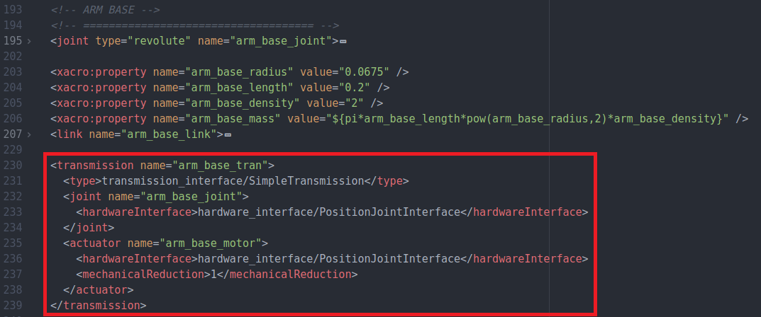
Transmission
In order to control the joint of the robot arm we have to define what type of transmission we want to use for each motorized joint by adding the following example code in your mobile_manipulator_robot.urdf.xacro file positioned after the joint and link definition as visualized in the image below:
  <transmission name="TRANSMISSION_NAME">
    <type>transmission_interface/SimpleTransmission</type>
    <joint name="JOINT_NAME">
      <hardwareInterface>hardware_interface/PositionJointInterface</hardwareInterface>
    </joint>
    <actuator name="MOTOR_NAME">
      <hardwareInterface>hardware_interface/PositionJointInterface</hardwareInterface>
      <mechanicalReduction>1</mechanicalReduction>
    </actuator>
  </transmission>
It must be stated, that this example implements a transmission with a joint position controller. More information on the transmission definition and the different controller types can be found on the official ROS website.
ROS parameter definition
The ROS controller_manager package needs the transmission joints defined as ROS parameters which we do in the joint_controller.yaml file which is located in the config folder. Copy the following example code in that file:
ROBOT_NAME:
  # Publish all joint states -----------------------------------
  joint_state_controller:
    type: joint_state_controller/JointStateController
    publish_rate: 1000

  # Controller
  CONTROLLER_NAME:
    type: position_controllers/JointPositionController
    joint: JOINT_NAME

  # Controller
  CONTROLLER_NAME:
    type: position_controllers/JointPositionController
    joint: JOINT_NAME
Replace ROBOT_NAME with the name you already used in the beginning of the Robot Arm section. CONTROLLER_NAME can be chosen freely but needs to match the launch file definition later in this section. JOINT_NAME needs to be the name of the joint defined in your mobile_manipulator_robot.urdf.xacro file. Add as many controllers as you have motorized joints.
Finally we need to add the following code to our robot_spawn.launch file to include the controller_manager package during startup. Make sure to change ROBOT_NAME and CONTROLLER_NAME to the appropriate values. And again, depending on how many motorized joints you have, you might need to add extra CONTROLLER_NAME references.
  <node pkg="robot_state_publisher" type="robot_state_publisher" name="robot_state_publisher" output="screen">
    <param name="publish_frequency" type="double" value="100.0" />
    <param name="tf_prefix" value="mobile_manipulator" />
  </node>

  <rosparam file="$(find custom_robot_tutorial)/config/joint_controller.yaml" command="load"/>

  <node name="controller_spawner" pkg="controller_manager" type="spawner" respawn="false" output="screen" ns="ROBOT_NAME"
    args="joint_state_controller CONTROLLER_NAME CONTROLLER_NAME"/>
Controlling the robot arm
The controller_manager subscribes to one topic for each perviously defined motorized joint. The topic names have the following syntax:
/ROBOT_NAME/CONTROLLER_NAME/command
An example of the topic names used in my example is shown in the following image:

To test if the control of the robot arm is working, you can use the following terminal command. After copying the command in a terminal, change the TOPIC_NAME according to the syntax previously explained press the tabulator key a view times to autocomplete the message.
rostopic pub TOPIC_NAME
Matlab Controller
This section will go into detail on how to control the Gazebo model with a MATLAB script.
Kinematic Model
The following code creates a standard kinematics representation of the robot arm, where “T” stands for translation and “R” stands for rotation. “x”, “y” and “z” define that the rotation or translation is around/along that axis of the base frame. The last code line plots the robot in the state with the defined joint angles.
close all
import ETS3.*

L1=0;
L2=0.2;
L3=0.385;
L4=0.270;
L5=0.115;

robot_normal = Tz(L1) * Rz('q1') * Tz(L2) * Ry('q2') * Tz(L3) * Ry('q3') * Tz(L4) * Ry('q4') * Tz(L5);
robot_normal.plot([0,0,0,0])
DH Parameters
Another way of describing the kinematic model of a robot is to use the Denavit-Hartenberg Parameters. The following code shows an example of the syntax used to do this in MATLAB:
close all
import ETS3.*

j1 = Revolute('d', L2, 'a', 0, 'alpha', -pi/2, 'offset', 0);
j2 = Revolute('d', 0, 'a', -L3, 'alpha', 0, 'offset', pi/2);
j3 = Revolute('d', 0, 'a', -L4, 'alpha', 0, 'offset', 0);
j4 = Revolute('d', 0, 'a', -L5, 'alpha', 0, 'offset', 0);

robot = SerialLink([j1 j2 j3 j4],'name', 'my robot');

robot.plot([0,0,0,0])
Forward/Inverse Kinematics
The following code lines give an example of how to compute the forward and inverse kinematics for the previously created DH model of the robot. The first line computes the transformation matrix given the joint angles of each motorized joint. The second line calculates the transformation matrix given the end-effector position and orientation. The third line computes the joint angles given one of the two previous transformation matrices.
T_robot_1 = robot.fkine([0,pi/2,pi/2,0])
T_robot_2 = SE3(0.385,0,-0.185) * SE3.rpy(0,0,90, 'deg')
qi = robot.ikine(T_robot_1, 'mask', [1 1 1 0 0 0])

robot.plot(qi)
ROS in MATLAB
ROS allows different programs to communicate with each other. The following code gives an example of a ROS node written in MATLAB which subscribes to the Odometry topic from the robot and publishes movement commands to the mobile platform as well as the joints of the robot arm:
rosinit
global odom

sub_odom = rossubscriber("/odom",@odom_callback);

[pub_q1,msg_q1] = rospublisher('/mobile_manipulator/base_joint_position/command','std_msgs/Float64');
[pub_q2,msg_q2] = rospublisher('/mobile_manipulator/link_1_joint_position/command','std_msgs/Float64');
[pub_q3,msg_q3] = rospublisher('/mobile_manipulator/link_2_joint_position/command','std_msgs/Float64');
[pub_q4,msg_q4] = rospublisher('/mobile_manipulator/link_3_joint_position/command','std_msgs/Float64');
[pub_vel,msg_vel] = rospublisher('/cmd_vel','geometry_msgs/Twist');

%scandata = rosmessage("std_msgs/Float64")
q_temp = [0,0,0,0];

msg_vel.Linear.X = 0.5;
msg_vel.Angular.Z = -0.5;

rate = robotics.Rate(1);
while rate.TotalElapsedTime < 10
    odom.Pose.Pose.Position

    if q_temp(2) == qi(2)
        q_temp = [0,0,0,0];
    else
        q_temp = qi;
    end

    msg_q1.Data = q_temp(1);
    msg_q2.Data = q_temp(2);
    msg_q3.Data = q_temp(3);
    msg_q4.Data = q_temp(4);

    send(pub_q1,msg_q1)
    send(pub_q2,msg_q2)
    send(pub_q3,msg_q3)
    send(pub_q4,msg_q4)

    send(pub_vel,msg_vel)

    waitfor(rate);
end

msg_vel.Linear.X = 0.0;
msg_vel.Angular.Z = 0.0;
send(pub_vel,msg_vel)

rosshutdown

function odom_callback(src,msg)
    global odom
    odom = msg;
end
To give more details on what the code does we will examine it line by line.
rosinit
This initiates a ROS Node
sub_odom = rossubscriber("/odom",@odom_callback);
Creates a subscriber which invokes the “odom_callback” function whenever a node publishes on the “/odom” topic. The function definition is at the end of the MATLAB SCRIPT.
[pub_q1,msg_q1] = rospublisher('/mobile_manipulator/base_joint_position/command','std_msgs/Float64');
Creates a publisher object “pub_q1” and a message object “msg_q1”. The publisher object is used to send data to the topic with the name “/mobile_manipulator/base_joint_position/command”. The message object is from message type “std_msgs/Float64” and will later be used to contain the data which is sent by the publisher.
msg_vel.Linear.X = 0.5;
The message type “Twist” has a sub-object Linear which has a sub-variable “X”. The value “0.5” is assigned to that variable.
rate = robotics.Rate(1);
Defines a Rate object which in combination with the code “waitfor(rate);” at the end of the while loop ensures that the loop runs at a frequency of 1 Hz (1 message per second).
rate.TotalElapsedTime
Time elapsed since the creation of the Rate object in seconds.
msg_q1.Data = q_temp(1);
Saves the content of the first element in the “q_temp” array inside the “Data” element of the message object “msg_q1”.
send(pub_q1,msg_q1)
Sends the message object “msg_q1” through the publisher object “pub_q1” to the previously defined topic.
rosshutdown
Shuts down the previously initiated ROS node.